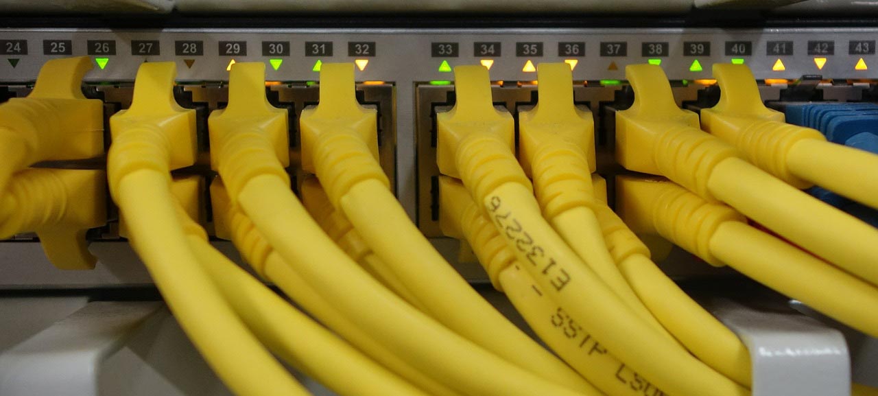
To make you more familiar with the concepts of network switching and to get acquainted with the reputable vendors of network switches, we have prepared a number of blogs as a series, the different parts of which are as follows:
- Part 1 – What is a Network Switch? Switching Terms (Such as Blade Server, Half Duplex, and Full Duplex)
- Part 2 – What is a Network Switch? Switching Terms (Such as PoE, VLAN, and STP)
- Part 3 – Types of Categories of Switches, Such as Stackable Switches, or Access Layer Switches
- Part 4 – Cisco Switches: Concepts, Blade Switches, and Campus LAN Switches (Access)
- Part 5 – Cisco Switches: Campus LAN Switches (Terms, Core and Distribution), and Data Center Switches
- Part 6 – Cisco Switches: Other Switches (Industrial Ethernet, InfiniBand , Small Business, Service Provider (Aggregation, and Ethernet Access)
- Part 7- Mikrotik Switches: Terms, and Also Switches such as RB260GSP, or CRS305-1G-4S+IN
- Part 8 – HP Switches: Terms, and Access Switches ( Such as Aruba CX 6400 Series, and Aruba 5400R Series )
- Part 9 – HP Switches: Core & Data Center Switches ( Such as Aruba CX 8400 Series, and Aruba CX 8320 Series)
- Part 10 – Dell Switches: Concepts and Technologies, and PowerSwitch Managed Campus
- Part 11- Dell Switches: PowerSwitch Data Center Switches, and PowerEdge M-Series Blade Switches
In this series of blogs you will come across a variety of terms, abbreviations, concepts, and technologies. We have tried to explain the general concepts and terms as much as possible in the first three parts of this series. In the following sections, we assume that you have read these two sections and therefore we will not re-explain these concepts and terms in the following sections. Of course, each vendor also has a number of specific terms and concepts that are explained in blogs related to the same vendor’s products.
Last note, all the content as well as the images used in this series of blogs are taken from the official websites of the reviewed vendors (Cisco, Microtik, HP and Dell).
Part 1- What is a Network Switch?
The switch is the mainstay of a computer network. You can create a small network without a router, but you can never do that without a switch. Switch (and switching operation) have a wide range of concepts, types of categories (with different criteria), as well as classes. In this series of blogs, we try to cover this content as much as possible.
In these posts we have a mental premise: Everyone who reading these posts has enough understanding and knowledge about the different layers of OSI and TCP/IP architectural models and especially knows the difference between the roles and function of layers two and three.
What’s Network Switch?
A network switch (or Ethernet switch) is networking hardware that connects devices on a computer network by using packet switching to receive and forward data to the destination device.
Switches can be hardware devices that manage physical networks, as well as software-based virtual devices.
A network switch learns the identities of connected devices and then only forwards data to the port connected to the device to which it is addressed. In other words, Ethernet switches link Ethernet devices together by relaying Ethernet frames between the devices connected to the switches. They copy Ethernet frames from one switch port to another, based on the MAC addresses in the Ethernet frames. Each switch has a dynamic table (called the MAC address table) that maps MAC addresses to ports. With this information, a switch can identify which system is sitting on which port and where to send the received frame.

In the past there was a device called switching hub, sometimes simply called hub and sometimes even (mistakenly) switch. Of course, Hub is still produced and sometimes used, but we recommend that you do not use it and think that this device is extinct. Why? Because Hub forwards every frame they receives from each port immediately to all ports. All devices refuse to receive that frame, only the device that is the real destination of that frame, receives that frame. There is a terrible amount of wandering frames. The intensity of packet collisions in the frame is very high, the communication speed is very low, the communication is half-duplex, and there are also other disadvantages. But, each port on a switch is in a separate collision domain and can run in the full duplex mode, which means that hosts connected to a switch port can transmit to the switch at the same time that the switch transmits to them.
Concepts, Terms and Technologies
In the previous section, we used a number of terms that we think it would be better to provide explanations about those terms here so that the rest of the content is more understandable.
ACL: An ACL (access control list) is like a filter in networking. ACL specifies which users or system processes are granted access to the network. When an ACL is configured on an Ethernet interface, data passing through the interface will be allowed or denied according to the set ACL rules. Usually, there are different ACL types like standard ACL and extended ACL. There is no ACL by default, and if necessary, you must define and implement ACLs according to your needs and policies.
Address Learning: Switches make traffic forwarding decisions based on the 48-bit media access control (MAC) addresses used in LAN standards. Every port on a switch has a unique factory-assigned MAC address. The Ethernet interface located in each port of a switch runs in promiscuous mode. In this mode, the interface is programmed to receive all frames it sees on that port, not just the frames that are being sent to the MAC address of the Ethernet interface on that switch port. As each frame is received on each port, the switching software looks at the source address of the frame and adds that source address to a table of addresses that the switch maintains.
Aggregation: We suggest that you read this post to fully understand this concept: What Is Link Aggregation and Link Aggregation Switch?
BGP: It’s a popular routing protocol (or algorithm). Border Gateway Protocol (BGP) routers typically receive multiple paths to the same destination. BGP is a standardized exterior gateway protocol designed to exchange routing and reachability information among autonomous systems (AS) on the Internet.
Blade Server: This article on Wikipedia explains the concept of “Blade Server”. We recommend that you read it.
Campus LAN: This is a proprietary local area network (LAN) or set of interconnected LANs serving a corporation, government agency, university, or similar organization. In this context, a typical campus encompasses a set of buildings in close proximity. For example, all of the nodes in a campus network are interconnected by means of optical fiber media, taking advantage of Gigabit Ethernet or 10-Gigabit Ethernet technology.
Collision Domain and Broadcast Domain: First, what’s domain? A domain is a type of computer network in which all user computers, printer’s accounts, and other devices registered.
- Collision domain: It defines the set of devices on which their frames could collide. A collision happens when two separate devices simultaneously send a packet on the commonly shared network segment. The packets collide, and both devices require sending the packets again. The devices might include the devices of other IP subnetworks.
- Broadcast domain: This Domain contains all devices which can reach each other at the data link layer with the help of broadcast. Every port on a switch or in a hub should be in the same broadcast domain. Broadcast Domain is never limited to the specific IP subnetwork for all types of IP broadcasts.
Basically, two-packet collision occurs only in half-duplex networks. With the advancement of switch technology and the removal of hubs, fortunately today the collision domain is limited to each port of a switch device. This means that each port has a collision domain, and as a result, there will never be a collision between packets of two devices that are connected to different ports of a switch device.
By default, all devices connected to the ports of a switch together form a broadcast domain. As a result, each broadcast packet reaches all the devices connected to the switch ports, which greatly increases network traffic and reduces performance. For this reason, switch segmentation techniques, specifically the VLAN technique, are used to minimize broadcast domains.
Look at the scenario drawn in the figure below:

PC300 is trying to communicate with PC400 and sends a packet with the PC400’s destination MAC address. The packet arrives at the switch, which looks at the destination MAC address. The switch then searches that MAC address in its MAC address table. If the MAC address is found, the switch then forwards the packet only out the port connected to the frame’s destination. Hosts connected to other ports will not receive the frame.
Ethernet Frame: The term Ethernet frame refers to the contents of a single packet of data transmitted over an Ethernet connection. In the OSI model the frame is on the data link layer and is responsible for the error-free transmission and separation of the bit stream into blocks. An Ethernet frame must be at least 64 bytes for collision detection to work, and can be a maximum of 1,518 bytes.
Contents of an Ethernet frame are:

- Preamble: An identifying pattern that devices on the network use to detect incoming frames.
- Start frame: It is delimiter, and it also known as an SFD, and in fact only indicates the end of the preamble.
- Destination MAC address
- Source MAC address
- The EtherType field: This value representing either the length of the frame or the specific protocol type. In the OSI model, the network layer is important for connecting and providing network addresses.
- The payload (or Data): This field contains the actual data being transmitted.
- The FCS (frame check sequence) Field: A field for redundancy check used to ensure the frame data was not corrupted during transfer.
FTTX: Fiber to the x is a generic term for any broadband network architecture using optical fiber to provide all or part of the local loop used for last mile telecommunications. FTTX is a generalization for several configurations of fiber deployment, arranged into two groups:
- FTTP/FTTH/FTTB (Fiber laid all the way to the premises/home/building)
- FTTC/N (fiber laid to the cabinet/node, with copper wires completing the connection)
GbE: Gigabit Ethernet is a version of the Ethernet technology broadly used in local area networks (LANs) for transmitting Ethernet frames at 1 Gbps (1000 Mbps).
Half-duplex & Full-duplex: LAN communication can operate in two modes. Half-duplex and Full-duplex.
- In Half-duplex mode, devices cannot send and receive data simultaneously. A device can either Send data or Receive data only in a half-duplex. In this mode, one device sends the frame and all other devices in the collision domain listen for the Ethernet frame. Collision is a problem in half duplex networks.
- In Full-duplex mode, a device can send and receive Ethernet frames simultaneously. There is no collision detection in devices operating in full-duplex mode, since collision detection is not required.
Hubs only work in half-duplex mode, but switches work in full-duplex mode.
Hot-swap: It means the removal and replacement of an electronic device or module without powering down or shutting down the system.
HPCC: Or (High-Performance Computing Cluster) is an open source, data-intensive computing system platform. The HPCC system architecture includes two distinct cluster processing environments Thor and Roxie, each of which can be optimized independently for its parallel data processing purpose.
———————–
Sources:
Read other blogs related to this series:
- Part 2 – What is a Network Switch? Switching Terms (Such as PoE, VLAN, and STP)
- Part 3 – Types of Categories of Switches, Such as Stackable Switches, or Access Layer Switches
- Part 4 – Cisco Switches: Concepts, Blade Switches, and Campus LAN Switches (Access)
- Part 5 – Cisco Switches: Campus LAN Switches (Terms, Core and Distribution), and Data Center Switches
- Part 6 – Cisco Switches: Other Switches (Industrial Ethernet, InfiniBand , Small Business, Service Provider (Aggregation, and Ethernet Access)
- Part 7- Mikrotik Switches: Terms, and Also Switches such as RB260GSP, or CRS305-1G-4S+IN
- Part 8 – HP Switches: Terms, and Access Switches ( Such as Aruba CX 6400 Series, and Aruba 5400R Series )
- Part 9 – HP Switches: Core & Data Center Switches ( Such as Aruba CX 8400 Series, and Aruba CX 8320 Series)
- Part 10 – Dell Switches: Concepts and Technologies, and PowerSwitch Managed Campus
- Part 11- Dell Switches: PowerSwitch Data Center Switches, and PowerEdge M-Series Blade Switches

